The Marshall TSL122 / TSL 100 thermal bias drift repair page
Many TSL122 (TSL 100) users have reported and complained that the amp is not "stable":
When the amps becomes warm, the current from (one or more of) the EL34-tubes to the output-transformer is getting higher and higher until the amp collapses.
The EL34-tubes are getting red hot inside.
Then hopefully one fuse blows.
The reason for that is a phenomenon, called the "thermal bias drift".
JC Maillet has made a great site explaining and discussing the problem:
The Marshall TSL122 JCM2000 Repair/Mods Page
There are several posts on the Marshall-forum about this problem. The conclusion in general is to buy a new motherboard from Marshall. This might be easy and affordable in the UK, but not in other countries in the world. In Germany for example the Marshall distributor wants 200 Euros for that. Why spend 200 Euros, if you can repair the beast quite easily?
Here is the analysis of the problem and here are the pictures, what to do. In brief:
- Yes, it is in the first place a problem of the faulty epoxy-material of the motherboard.
- Yes, it also is a problem of the cheap resistors in the bias circuit (maybe in the phase-splitter also).
- The layout of the heater-supply of the EL34s should be enhanced, as you work inside the amp anyway.
Marshall has admitted, that the motherboard epoxy material ages and becomes faulty during normal use. The motherboard starts to act like a NTC (a resistor with a Negative Temperature Coefficient), which means that the isolating capabilities of the board-material are reduced once the board becomes hot. In other words: Some megaohms occur, where they definitely should NOT be... This is not a problem in most places of the motherboard. It happens mostly in the hottest spots of the motherboard. The hottest spots are the four areas where the tube sockets are soldered into the board. Let us check the situation there:
Assuming the motherboard had thermal stress over the years and had become faulty. Now there are megaohms between the pins of the tube sockets once the amp is getting hot. Let us find out first, where these bad megaohms are NOT a big problem:
It is obviously clear, that these megaohms do not or not much affect
- the area between pin 1 (Surpressor Grid - connected to GND) and pin 8 (Cathode - connected to GND), because these pins are connected anyway.
- the area between pin 1 (Surpressor Grid - connected to GND) and pin 2 (Heater), because there are 100 Ohms only (the 100 Ohms resistor that balances the AC voltage of the tube heaters to GND),
- the area between pin 8 and pin 7, because there are also 100 Ohms only (the other resistor that balances the AC voltage of the tube heaters to GND)
- the area between pin 7 and 6, because pin 6 is not existing,
- the area between pin 3 and 4, because these pins are connected via the 1 Kiloohm screen-grid-resistor.
Conclusion: Between these above mentioned points additional megaohms will not do much trouble. So let us find out finally, where these megaohms are a BIG problem. There are only two problem-zones left:
- the area between pin 2 and 3, because the high voltage above 400 Volts on pin 3 (anode) can affect the 6,3 V AC on pin 2. My tests show, that this area causes not the problem we are talking about.
- the area between pin 4 (high screen-grid-voltage above 400 Volts DC) and pin 5 (the negative bias-voltage of approx. -40 Volts DC).
Here - between pin 4 and pin 5 - is the big problem. Just imagine the horror that occurs to the negative bias-voltage, if there is any leakage going on from the high and positive screen grid voltage to the negative bias-grid-voltage. Even some megaohms between these two pins will affect the bias-voltage - and in these amps they do just that. The leakage causes the bias-voltage to drift to zero or even to a positive value. The effect is a tube-collaps. You can compare it with a water-pipe-burst in your kitchen.
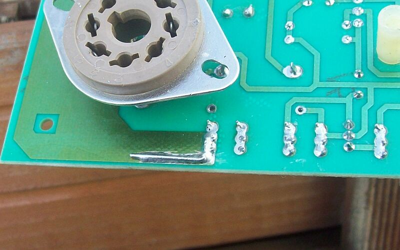
The easy solution is made with a dremel-tool. The surrounding area of pin 5 is milled away. After this procedure you can easily desolder the remaining stuff at all pins 5 of the sockets. Pin 5 of each socket has now a perfect isolator - air.
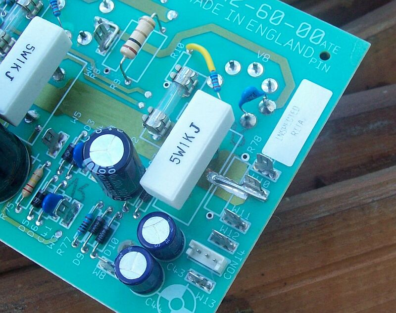
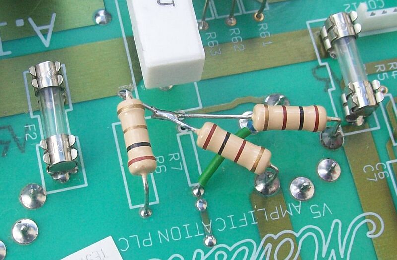
The pic shows that the cheap resistors in this area (R66 - R70) are replaced by Metal-Film-Resistors. You see that R66 and R70 are directly connected to the pins of the tube sockets. These resistors were 220k - a wrong value. The schematic (and my experience) tells that the right value for these resistors (bringing the sound to the output tubes and preventing FM-Radio interference) is 5k6 Ohms. The same thing has to be done with (not in the pic) the resistors R7 and R10.
Yes, I changed the resistors in the phase-splitter area also (no pic). But I assume that these resistors are not responsible for the thermal bias drift problem we try to solve here.
One word about the pic on the left side: You see a "bad-dremel-job". My dremel-tool got out of control and damaged the outer part of the hole around pin 5. The copper-strip next to the hole was damaged. I am glad it happend, because you can now replace this copper strip with a normal wire (seen completely in the last pic at the end of this text). The wire supplies GND (the ground of the negative bias-voltage). It is a good thing to have GND far away from the high voltages at pin 4 of the tube socket.
Ok. The thermal bias drift problem is fixed now.
Since you have the motherboard on your workbench anyway, you may want to improve the overall stability of the motherboard. I have seen TSL122 amps with a lot of damage at the edge of the motherboard - damage caused by the weak connectors supplying the heater-current. One EL34 sucks ca. 1,6 Amp. heating current (x 6,3 Volts = 10 Watts!) out of the power supply. So all four EL34s suck more than 6 Amperes. That is a lot. It needs to be observed.
Marshall has decided to save costs - that means here: to use copper-strips on the motherboard as the wire for the heater current. Look at the motherboard and let light shine on it and through it: You might see - like I did - that the copper strips have partly chanced their color a little bit. This discoloration happens mostly at the edge of the motherboard where the connectors (to the power-transformer) are located. It is obvious, that these points are "weak" and need a better connection to deal with more than 6 Amperes heater current.
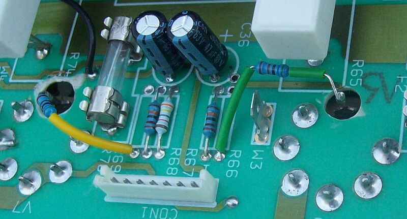
The following two pictures show what I did. I scraped off a little bit of the green protective lacquer and soldered a little wire between the post and the copper-strip. This prevents further damage to the motherboard and gives the tubes the "food" that they need.
To do this job on the component side of the motherboard you need to desolder the 100 Ohms resistor R78. This resistor and the resistor R8 (also 100 Ohms) balance the heater-filaments to GND. I decided not to solder these resistors back into their former place. I soldered them to the sockets at tube V5 - as seen in the pic below.
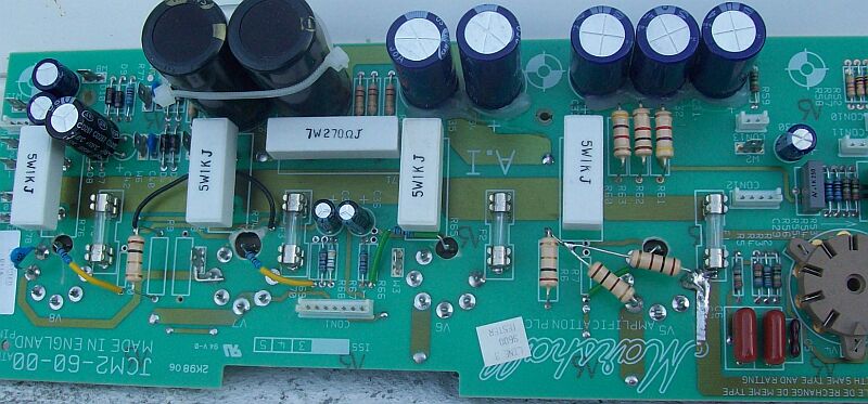
Finally - here is a pic of the complete repaired and modified motherboard. I reassembled the amp and gave it back to my friend Ralph. He uses this amp almost daily now - with a better sound (due to the 5k6 resistors mentioned) and without any thermal drift problems.
Keep rocking!
Fred